ICOM SP-41 becomes a power supply
++++ This is work still in process ++++
Many of you may know that you can NOT get the proper ICOM PS-126 to fit the IC-7610 in europe anymore. This is a real pitty, because it fits nicely to the ICOM line including speakers and everything. I also upgraded one SP-41 with the phonema kit: https://df7ee.de/icom-sp-41-speaker-modification/
Now the idea is to put a switched power supply inside the SP-41

First you need to remove 14 screws and remove all covers. The original speaker is mounted in a plastic box that needs to be removed completly.

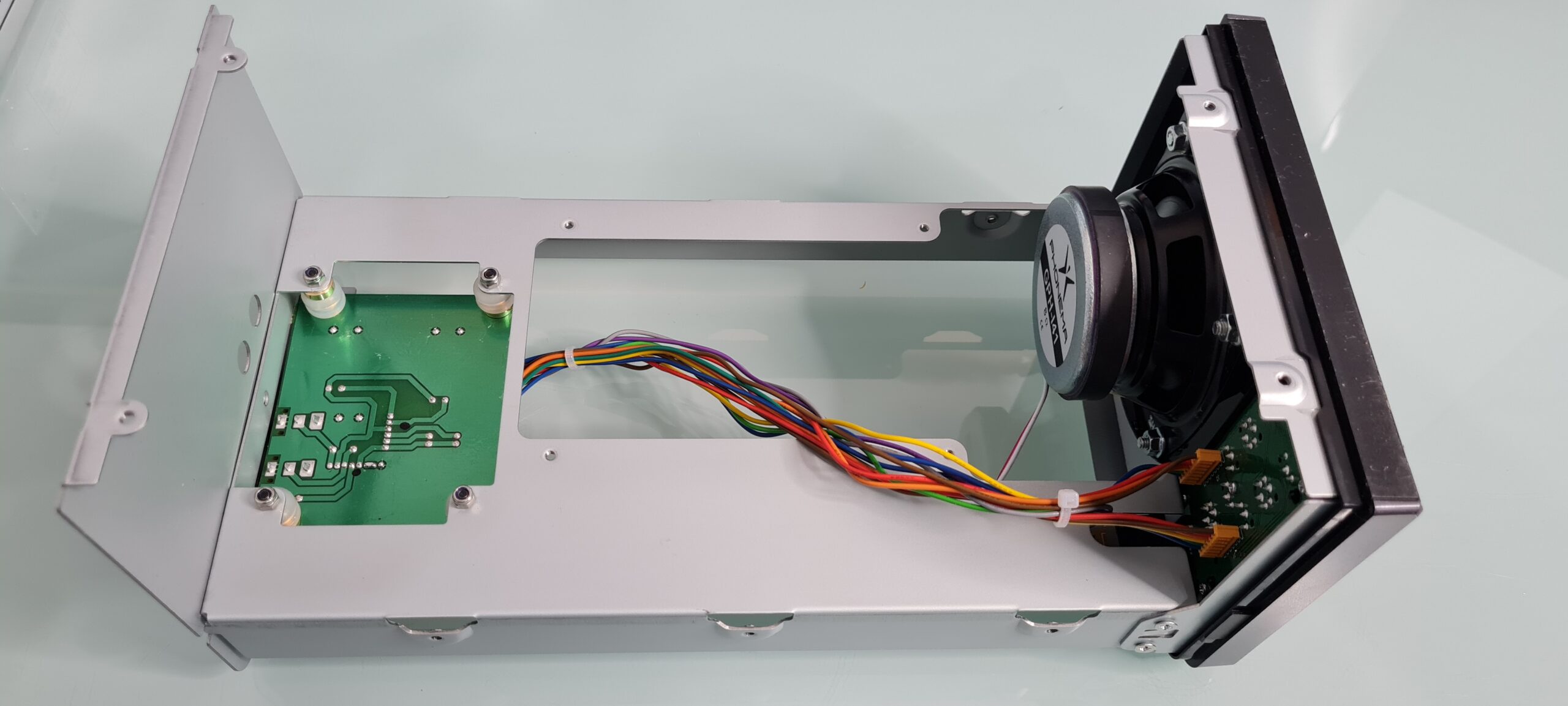
After removing the plastic tubes speaker I mounted the speaker that comes together with the phits kit from phonema to the front panel.

The little pcb board with the connectors on the rear end need to move from the top to the bottom of the cabinet in order to make space for the power supply.

I have used the metal stands that were used to the platic tube to make distance on the down side. You also need to drill two new holes on the back plate for the two 3.5mm inputs.

Now there is almost enogh space for a switching power supply to fit in. I used tape to store the cables a little bit better to not interfear with the rest of the project.

NOW there is onogh space for the 25€ power supply I bought from ebay.

From here on it gets a litle bit experimental – and I have planed to make it a litle bit nicer later on, but for a first HOT test this should be ok.
+++++ all you do is on your own risk +++++
I used the two original holes in the back to get the 230V AC cable in and the 13.8V DC cable out of the box.

Now connect everything to the power supply…..
I have adjustet the voltage to 13.8V as they usually come with a setting of 12V.
The power supply is rated 12V 25A

Now the power supply goes in upside down. Sorry – for the moment I just use tape to hold it in plce. Need to find a more professional solution.

Now there are two issues I need to fix:
1: I put the power supply upsde down in order to have the fan blowing toward the lower cabinet. I have planed to put a propper hole in there (invisible from above) to lead out the warm air from the power supply. I have to get a proper tool to do that. I also want to measure some live temeratures to find out what is going on inside. In case of high duty cycle RTTY or FT8 I can imagine there will be some heat that needs to get out!!!!!
2: I orderd proper terminals for the back side to connect DC directly instead of using cable.
Some more improvements also would be:
- Proper AC connector on the back – but I dont have the tools to do that cut in the rear metal.
- Proper AC Switch on the back – but again – no real tools to make the cutouts.
- Maybe also a air inlet on the back …..
This is work in progress and anything you do is at your own risk and expenses!!!!
NO WARRENTIE!!!
I keep updating this post as soon I got the parts to fix the temp issues.
73
Helmut
www.df7ee.de